IEC 60439-1
EN 60439-1
UL 508
CSA 22.2 part 14
94260116 Edition 1
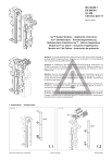
Iso™ Busbar Modules – Application Instruction
Iso™ Gerätemodule – Anwendungsanweisung
Modules Barre Collectrice Iso™ – Notice d‘application
Moduli Iso™ su sbarre – Istruzione d‘applicazione
Modulo Iso™ de Pletina – Instrucción de aplicación
Attention: To prevent electrical shock, disconnect from power source before installing or
servicing. Install in suitable enclosure. Keep free from contaminants. To be commissioned
and maintained only by qualified personnel!
Achtung: Vor Installations- oder Servicearbeiten Stromversorgung unterbrechen, um
Unfälle zu vermeiden. Die Geräte müssen in einem passenden Gehäuse eingebaut und
gegen Verschmutzung geschützt werden. Inbetriebsetzung und Wartung nur durch
Fachpersonal!
1
0
Attention: Avant le montage et la mise en service, couper l‘alimentation secteur afin
d‘éviter tout accident. Prévoir une mise en coffret ou armoire appropriée. Protéger le
produit contre les environnements agressifs. Mise en service en entretien: seulement par
du personnel spécialisé!
Attenzione: Per prevenire infortuni, togliere tensione prima dell‘installazione o manutenzione.
Installare in custodia idonea. Tenere lontano da contaminanti. Messa in servizio e
manutenzione solo da personale specializzato!
Atención: Desconectar la alimentación eléctrica antes de realizar el montaje y la puesta
en servico, con el objeto de evitar accidentes. Instalado en una caja o armario apropiado.
Proteger el produtcto de los ambientes agresivos. Puesta en servicio y mantenimiento
exclusivamente por personal especializado!
1. Components
Komponenten
0240-4-02
0121-4-02
AP***
AS9S
AS9S
AK
1.1
Technische Änderungen vorbehalten.
0105-06 © KHW
1.2
Stand 09.2003
0122-4-01
0072-4-01
Click
Click
1.4
1.3
2. Assembly of components
Aufbau Geräte
0113-4-02
1
0
M d = 0,5 – 0,8 Nm
3. Busbar System
M d = 0,5 – 0,8 Nm
2.1
Schienensystem
0112-4-00
0111-4-02
5,
12
25 , 15,
, 3 20
0m ,
m
10
mm
1
2
R=
0,5
mm
m
5m
60
5 mm
60
mm
Click
3
mm
10 mm
Technische Änderungen vorbehalten.
3.1
0106-05 © KHW
4
10
mm
3.2
Stand 06.2003
4. Assembly of the adapter
Montage Adapter
0124-4-02
0116-4-02
Click
1
0
4.2
4.1
5. Test position
Teststellung
0242-4-01
0115-4-01
4
3
2
1
1
1
0
1
0
2
0
1
M
5.2
5.1
0243-4-01
0244-4-01
Test
c
22 a.
mm
6
5
1
6
1
0
0
M
5.3
Technische Änderungen vorbehalten.
0107-06 © KHW
5.4
Stand 10.2003
6. Disassembly of the device adapter plate
Demontage des Gerätemoduls
0118-4-02
0068-4-03
1
Click
1
3
0
2
6.1
7. Reconnection of the device adapter plate
Montage des Gerätemoduls
0119-4-02
0120-4-02
1
1
0
0
7.1
Technische Änderungen vorbehalten.
6.2
0108-05 © KHW
7.2
Stand 06.2003
">